What adding ribs adds up to
Adding ribs to injection molded plastic parts is a common design principle.
Let's have a look at what the effect of adding ribs really is.
Now, plastic is a relatively weak material. Making a plastic part strong enough requires consideration.
The injection molding process requires even wall thickness.
Simply increasing the wall thickness comes at a penalty. Not just the additional material, but above all the increased cycle time. Doubling the wall thickness quadruples the cooling time.
So, adding ribs seems to be the sensible thing to do when more strength is required.
And it often works very well. But not always.
To study the effect of ribs, we have made Finite Element Method (FEM) calculations of a few simple models:
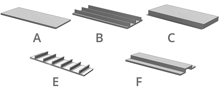
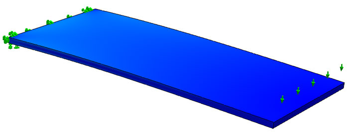
Model A represents a flat plastic surface without ribs.
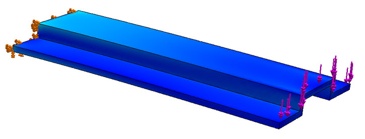
Model B is the exact same surface, with three added ribs.
These ribs follow the common design rule; the thickness of these ribs is 0.7 times the wall thickness of the surface.
Model C is, again, the same surface but now as thick as the wall thickness and the height of the ribs combined.
Because adding ribs is a means of getting some of the benefits of the greater wall thickness, this makes interesting comparison.
Model E is identical to Model B, but with the ribs in the other direction.
Model F has the same dimensions as model B, but with “zig-zag” or sheet-piling type ribs.
(Yes, there's no model D)
When is a part strong enough?
In order to determine if a part is strong enough, one must determine how much stress is induced by the expected load or the expected deformation.
If the calculated stress is higher than the maximum (tensile) stress specified for the material, the part is likely to fail.
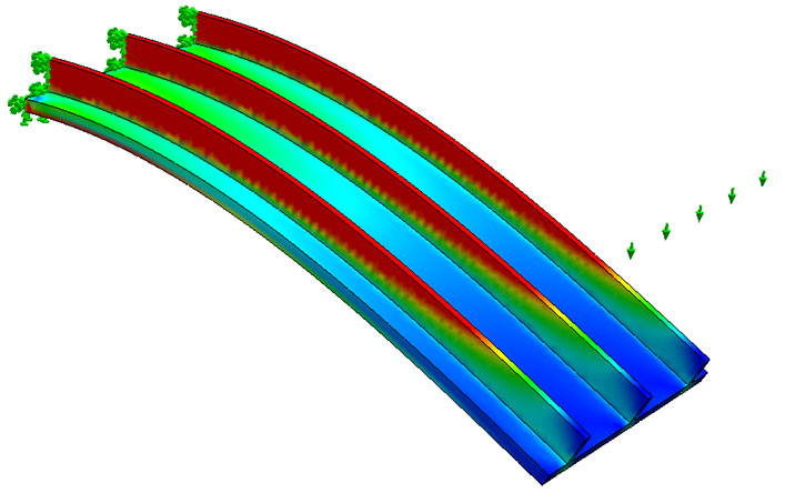
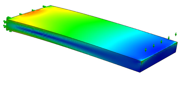
The illustrations below show the results of the FEM calculations. The color scale is kept in the same range for each illustration.
Blue is low stress, green medium and red indicates a high stress.
First, we are going to compare how the three models behave under the same load.
We fixate the models on one end and apply a downward force on the other end.
Green arrows = Fixation
Purple or brown arrows = Force (load)
Model A.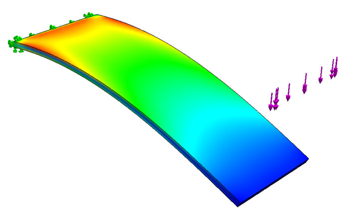
Case1
Model B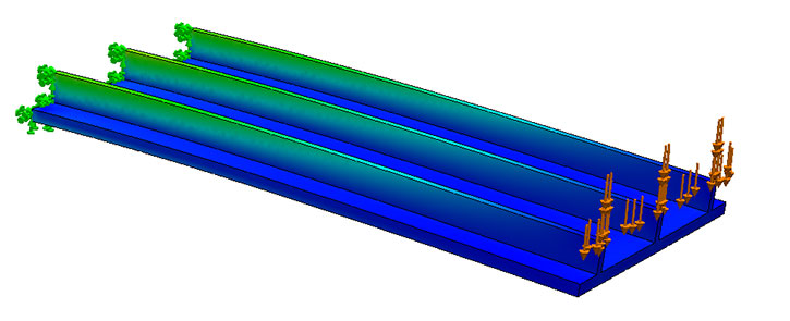 Case 2
Although the force is the same, the displacement is much smaller, and the stresses in the material are much lower.
Model C 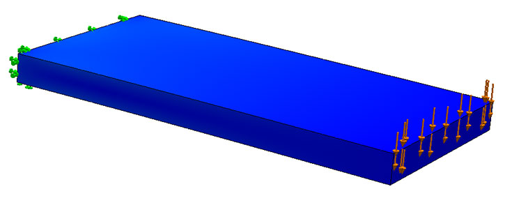
Case 3
Under the same load there is hardly any displacement and the stresses are very low.
First conclusions
Under same-force conditions model B is much stiffer and stronger. But not nearly as stiff and strong as model C.
Model B, reversed load
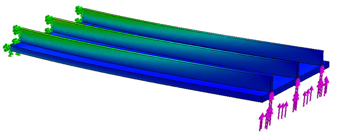
Case 4
Same conditions as above, but now the force is pushing upwards. The resulting stresses and the displacements are the same.
Compression stress vs tensile stress
But in this case the highest stresses are compression stresses. In practice under compression a plastic tends to be a bit stronger, because cracks are less likely to be initiated.
By comparison, under tensile stress once a crack is initiated, things will get from bad to worse.
Model E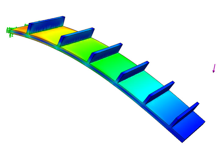
Case 5
Obviously, the direction of the ribs matters. Perpendicular to the induced stress they are not of much use. This model E behaves almost identical to model A
In other words, adding these ribs does not help at all.
A much stronger version of ribs
Model F
Case 6
In this version the ribs have normal wall thickness and alternating the wall is moved to the top of the ribs.
They are easier to mold and are a much more robust solution.
These sheet piling type ribs cannot be used if there are esthetical requirements for an uninterrupted surface.
Comparing how the three models behave under the same displacement.
In these calculations we fixate one end and push the opposite end down to a pre-determined displacement.
Often a construction needs to have a certain flexibility rather than withstand a certain force.
A snap fit construction would be an example.
Model A
Case 7
Here we subject the part to the displacement that Model B had in case 2.
Much less force is needed and stresses are very low.
Model B
Case 8
We subject this model to the displacement that Model A had in case 1.
The resulting stress is very high. Adding the ribs in this case would make matters worse and could indeed lead to failure.
In this case the part would be stronger without ribs
Model C
 Case 9
In order to get it to bend as far as Model B in case 2, a very much higher force is required.
The stresses are also much higher.
Conclusions.
When a part is submitted to a certain load, a weight for example, adding ribs can be very beneficial.
![]() It can be used to add strength and stiffness.
It can be used to add strength and stiffness.
![]() In order to be effective ribs must be placed in the right directions.
In order to be effective ribs must be placed in the right directions.
![]() When a part is submitted to a certain displacement, as a rule ribs are counterproductive.
When a part is submitted to a certain displacement, as a rule ribs are counterproductive.
Under these circumstances the ribs actually weaken the part. In practice parts are often submitted to both kind of load situations.
![]() This means ribs must be added with care and understanding.
This means ribs must be added with care and understanding.
![]() For various reasons, sheet piling type ribs are more suitable to the injection molding production process. When design circumstances allow, they should be considered. (model F)
For various reasons, sheet piling type ribs are more suitable to the injection molding production process. When design circumstances allow, they should be considered. (model F)
Main cases
All calculated cases